Black-box 5000 User Manual
Browse online or download User Manual for Computers Black-box 5000. Black Box 5000 User Manual
- Page / 268
- Table of contents
- BOOKMARKS
- Multiserver 5000 1
- Table of Contents 10
- Table of Contents (continued) 10
- 1. Specifications 14
- Async Channel Characteristics 15
- Sync Channel Characteristics 15
- Multiserver 5000 (continued) 15
- MS1 Voice/Fax Cards 17
- General Specifications 17
- Analog Specifications 17
- CHAPTER 1: Specifications 18
- Signaling Specifications 18
- Digital Specifications 18
- MS1 56K CSU/DSU Module 19
- MS RLB Module 19
- MS1 NMS Module 20
- MS1 V.35 Converter/DCE 20
- X.21 Converter/DCE 20
- 2. Introduction 21
- CHAPTER 2: Introduction 22
- 2.2 Feeder Muxes 22
- 2.12 Manual Text Conventions 26
- Default Node Default Node 29
- Unit Number ID 29
- INGLE LINK POINT-TO-POINT 31
- DISTRIBUTED STAR 35
- 4. Base-Unit Installation 36
- Warning! 37
- Channel Numbers 39
- 5. Module Installation 42
- 5.4 Blank Back Panel 45
- 5.5 Disassembly Procedures 45
- NUMBER 1 47
- 5.6 Installation Procedures 49
- DIMPLES ON TOP OF BACK PANEL 51
- BLANK BACK PANEL 51
- NSTALLING CONVERTERS 53
- EMOVING CONVERTERS 53
- 6. Getting Started 54
- CHAPTER 6: Getting Started 55
- 6.3 The Command Facility 55
- 6.4 Reset Defaults 57
- 6.5 Name the Local Node 58
- 6.6 Quick Setup 60
- 1 2 3 4 5 6 7 8 9 10 11 1212 63
- EZ423 EZ423 65
- Crossover Cable 65
- 7.4 The Sync Data Channel 66
- (DTE, DB25) 67
- MS RLB COMMPAK 69
- Local Multiserver 69
- Remote Multiserver 69
- 7.6 Testing the RLB Module 70
- 7.7 Voice/Fax Channels 71
- 8.1 Types of Links 72
- 8.2 Avoid Node Duplication 72
- CHAPTER 8: Link Configuration 75
- 9. Data-Channel Configuration 84
- ONTROL SIGNALS 87
- Protocol Data Rate (bps) 91
- Multiserver DTE 93
- Constant Controlled 93
- 9.3 Asynchronous Channels 95
- Option Default Description 101
- 9.4 Copy Channel Parameters 104
- 10. Switching Configuration 108
- Option Description 109
- Important! 111
- 10.4 Synchronous Connections 113
- ODE/CLASS CONNECTION 115
- ATRIX CONNECTION 115
- Channels 116
- Parameters 117
- 10.8 Classes 120
- Async Channel 131
- 11. Administration 132
- CHAPTER 11: Administration 133
- Table 11-1. Reset Options 134
- 11.2 The Command Mode 135
- Table 11-2. The Command Mode 136
- 11.4 Messages 142
- Table 11-5. Dialog Messages 144
- 11.5 Network Security 146
- 11.6 Status/Statistics 148
- 11.7 Link Administration 156
- 11.8 Channel Administration 156
- 12. Diagnostics 159
- CHAPTER 12: Diagnostics 161
- Facility 161
- 12.5 Testing the Network 165
- 13. LCD/Keypad 167
- LCD/Keyboard Menu Flow Chart 169
- 13.2 Banner Message Display 170
- CHAPTER 13: LCD/Keypad 171
- 13.4 Menu Functions 171
- 13.5 Administration 171
- Important 172
- 13.7 Configuration 176
- Appendix A: Worksheets 177
- Display Messages Worksheet 190
- Record of Passwords 192
- Appendix B: Cabling Diagrams 193
- LEAVE A1 EMPTY 206
- RJ-48 CONNECTOR 206
- RJ-48 AT BOTH ENDS 206
- OF CABLE 206
- Cabling for the NMS Module 207
- (RS-232) 208
- CONVERTER 208
- (EHN071-005M) 210
- Cabling for Use with Tandem 212
- Appendix C: Defaults 213
- Voice/Fax Module 220
- Voice/Fax Module (continued) 221
- NMS Module 222
- Appendix D: Messages 223
- Screen Display Messages 224
- LCD Messages 236
- Appendix E: Indicators 241
- HP ENQ/ACK 247
- Table F-1. Spool Mode 248
- TOP VIEW 249
- MULTISERVER 5000 250
- Glossary 254
- Review System Message Log 266
- Menu Functions (password) 266
- Menu Flow Diagram 267
Summary of Contents
Order toll-free in the U.S. 24 hours, 7 A.M. Monday to midnight Friday: 877-877-BBOXFREE technical support, 24 hours a day, 7 days a week: Call 724-74
Table of Contents9Dialog Messages...
Multiserver 500098CHANNEL FEATURESThe Channel Features Menu is accessed from theAsync Channel Menu as option 2. Additional interface parameters associ
CHAPTER 9: Data-Channel Configuration99Table 9-11. Asynchronous Channel FeaturesOption Default Description1. Priority High Determines whether port is
Multiserver 5000100disconnect the channel in the event of loss of sync on the link.Table 9-11. Asynchronous Channel Features (continued)Option Default
CHAPTER 9: Data-Channel Configuration101EXTENDED FEATURESThe Extended Features Menu is accessed from theAsync Channel Menu as option 3.The current con
Multiserver 50001029.4 Copy Channel ParametersBy using the Copy Channel Parameters selection,you can configure a range of sync or async ports ora sin
CHAPTER 9: Data-Channel Configuration1039.5 Review Data-Channel ConfigurationREVIEWING SYNC-CHANNEL CONFIGURATIONTo review sync-data channels, enter
Multiserver 5000104REVIEWING ASYNC-CHANNEL CONFIGURATIONTo review async-data channels, enter the ViewConfiguration menu.At this prompt, enter the node
CHAPTER 9: Data-Channel Configuration1059.6 Connecting Data Channels CablesIn Appendix B, there are cabling diagrams thatshow each type of cable you
Multiserver 5000106This chapter discusses switching configurations forsynchronous and asynchronous data channels.Information on configuring Voice/Fax
CHAPTER 10: Switching Configuration107Table 10-1. Switching Control (continued)Option Description2. Enable Channel This option returns an out-of-serv
Multiserver 50001013. LCD/Keypad13.1 General LCD/Keypad Information ...165
Multiserver 5000108Table 10-1. Switching Control (continued)Option Description4. Force Disconnect Disconnects two ports which have been force-connect
CHAPTER 10: Switching Configuration10910.2 Point-to-Point Dedicated (Force ConnectAll)This function is designed for a single interconnectlink point-t
Multiserver 5000110disconnecting ranges, see Section 10.3, ForceConnecting a Range.10.3 Force-Connecting a RangeThe procedures for force-connecting a
CHAPTER 10: Switching Configuration111voice-voice, async-async, sync-sync connections willbe made.If the “from” range is greater than the “to” range,t
Multiserver 500011210.5 Asynchronous ConnectionsThe following five methods of switching aresupported for async ports:Force The network operator confi
CHAPTER 10: Switching Configuration113and then for an available port in the secondaryclass.The following steps are used to make a classconnection.1. A
Multiserver 5000114Note: The wild card (*) can be used to access arange of ports. To access any async port in theMultiserver identified by the nameN
CHAPTER 10: Switching Configuration11510.7 Asychronous-Channel SwitchingParametersControl of async-channel switching capability isconfigured through
Multiserver 5000116Table 10-2. Switching ParametersOption Default Description1. Connect Protocol Dedicated Selects the communication protocol used.
CHAPTER 10: Switching Configuration117Table 10-2. Switching Parameters (continued)Option Default Description7. Resource Class None This option includ
Table of Contents11Display Messages Worksheet...188Voic
Multiserver 500011810.8 ClassesWHATISASWITCHING CLASS?A class is a group of one or more ports that may beused for similar purposes by network users (
CHAPTER 10: Switching Configuration119MULTISERVER 5000PBXHOSTFAXASYNC TERMINALCOMMAND FACILITYMULTISERVER 1000MULTISERVER 1000MULTISERVER 1000To C1 an
Multiserver 5000120EXAMPLE OF A SWITCHING CLASSFigure 10-4 shows a Multiserver network. TheCentral Office has a Multiserver 5000 with a 6-channel CEM
CHAPTER 10: Switching Configuration121The Class Parameters menu appears:Each of the menu options are explained in Table 10-3.To include a port as part
Multiserver 5000122Table 10-3. Class Configuration (continued)Option Default Description3. Class Password None Password protection is available for a
CHAPTER 10: Switching Configuration123Table 10-3. Class Configuration (continued)Option Default Description5. Class No Activity 0 The no activity fea
Multiserver 500012410.9 Connect Protocol DetailsConnect protocol is option 1 of the SwitchingParameters menu. There are three connectprotocol optio
CHAPTER 10: Switching Configuration125For Dual portIdle State: DTR can be high or low. TheMultiserver holds DSR, CTS, CD,and RI low.1. Multiserver ra
Multiserver 5000126orInitiated by Multiserver (or remote end):1. Calling device disconnects. 2. Multiserver drops CTS, DSR, and CD. 3. Port is marked
CHAPTER 10: Switching Configuration12710.11 X.21 Switching ConsiderationsThere is no special async channel configurationrequired for use with X.21, w
Multiserver 500012Fast Packet ...
Multiserver 5000128For additional information on configuring yourport parameters, refer to Section 9.3, AsychronousChannels, and for classes, refer to
CHAPTER 10: Switching Configuration12910.12Review Switching Configuration for anAsync ChannelTo review the switching parameters of asyncchannels, ente
Multiserver 5000130System administration can be done through thededicated command port on the NMS module or afloating command port. This chapter assum
CHAPTER 11: Administration131After you have entered the correct channel, pressthe EXEcute key.To reset to a Default or Current Configuration,press the
Multiserver 5000132Table 11-1. Reset OptionsOption Description1. Node Disconnects the Command Facility and resets the local Multiserver node, all loca
CHAPTER 11: Administration13311.2 The Command ModeThe Command Mode is a single menu whichsupports configuration and testing of the local portand acce
Multiserver 5000134Table 11-2. The Command ModeOption Description1. Async Channel A selection of loopback tests. See Section 12.3, Async Channel Loopb
CHAPTER 11: Administration13511.3 Configuring the Command FacilityThe Command Facility Parameters Menu controlsthe system time, date, system reports,
Multiserver 5000136Table 11-3. Command Facility ConfigurationOption Default Description1. Time 00:00:00 The system time. At power-up, the Multiserver
CHAPTER 11: Administration137Table 11-3. Command Facility Configuration (continued)Option Default Description6. Periodic Reporting 60 Defines the inte
CHAPTER 1: Specifications13Multiserver 5000 (Base Unit)MX219APerformance SpecificationsMultiplexor Technique — Fast Packet MultiplexingCapacity —Data
Multiserver 5000138Table 11-3. Command Facility Configuration (continued)Option Default Description8. Output Periodic Local Remote Node. Periodic repo
CHAPTER 11: Administration139Table 11-3. Command Facility Configuration (continued)Option Default Description11. External Modem None Enter the charact
Multiserver 500014011.4 MessagesALARM MESSAGESAlarms generally indicate that an error has beendetected that impacts or degrades the performancefor pa
CHAPTER 11: Administration141will accept the entry, and the following promptappears:Enter up to 45 characters, including spaces andpunctuation. Specia
Multiserver 5000142Special rules apply when entering the characterslisted in Table 11-4 in a dialog message.Length: Dialog Messages vary inmaximum len
CHAPTER 11: Administration143Table 11-5. Dialog Messages (continued)MaxOption Default Char Description11. Unassigned UNASSIGNED 17 Sent when a node,
Multiserver 500014411.5 Network SecurityProtecting selected portions of the Command Modeand the Command Facility involves two types ofsecurity: pass
CHAPTER 11: Administration145LOCK-OUT CONFIGURATIONThis type of security blocks access to either theCommand Facility or the Command Mode. Theasync cha
Multiserver 500014611.6 Status/StatisticsStatus and statistics reports are available on theStatus/Statistics Menu. Status is a snapshot of thesystem
CHAPTER 11: Administration147Table 11-7. Status/Statistics (continued)Option Description2. Channel Status(continued)3. Interface Status This option i
Multiserver 5000 14Async Channel CharacteristicsCapacity — up to 41Speed — 50 to 38,400 bpsConfiguration — DCEABR — to 19.2 KbpsParity — Odd, Even, Ma
Multiserver 5000148Table 11-7. Status/Statistics (continued)Option Description4. Queue Status Lists all the class numbers, class names, and the node
CHAPTER 11: Administration1495. Voice/Fax Status If the Multiserver is equipped with a voice/fax module, this option will display a range ofports sele
Multiserver 5000150Table 11-7. Status/Statistics (continued)Option Description7. System Statistics Provides two options: the period report (the repo
CHAPTER 11: Administration151Table 11-7. Status/Statistics (continued)Option DescriptionSystem status is displayed as a set of statistics in a single
Multiserver 50001527. System Statistics The Mux Link and the X.21 Link:(continued)[node id] CONNECT STATISTICSCONNECT MAXIMUMCLASS NAME
CHAPTER 11: Administration153Table 11-7. Status/Statistics (continued)PROM ID = 907-2154-00 XENTER CARRIAGE RETURN TO CONTINUE Revision Level
Multiserver 500015411.7 Link AdministrationRESETIf a link is not working properly (interconnect,mux, or X.21), it can be reset. If the other end ofth
CHAPTER 11: Administration15511.9 Switching AdministrationMonitoring the switching functions of your networkis critical for high-efficiency network p
Multiserver 5000156Table 11-7. Status/Statistics (continued)Option Description8. Channel Statistics Channel Statistics are part of the System Statist
CHAPTER 12: Diagnostics15712.1 Self-TestThe self-test checks the operation of all systemmemory. The Multiserver automatically executes aself-test wh
CHAPTER 1: Specifications15Expansion ModulesMS5 Expansion Module Sync/AsyncMX215CConnectors — (6) DB25 (female)Interface — RS-232, V.24/V.28Transmissi
Multiserver 5000158test. The integrity of the components involved inthe test can be judged by observing the quality ofthe returned data (see Figure 1
CHAPTER 12: Diagnostics15912.4 System Diagnostics in the CommandFacilityThe system administrator may perform all of thefollowing diagnostics from the
Multiserver 5000160Enter the channel to be tested. Press <cr>. These tests are performed only on async ports fromthe user terminal. The menu
CHAPTER 12: Diagnostics161The Fox Message Test causes a continuous foxmessage to be output to the test port. The port thatis being tested will not be
Multiserver 5000162The following menu will appear:After the test is initiated, the Command Facilityterminal will be returned to the Command Facilityma
CHAPTER 12: Diagnostics16312.5 Testing the NetworkIn a Multiserver network, there are several loopbackand test-pattern tests that you can use to diag
Multiserver 50001643. You may do either one of the following setups:a. • Select remote echo (option 2).• Attach an async tester (i.e., a BERT) tothe a
CHAPTER 13: LCD/Keypad16513.1 General LCD/Keypad InformationThe Multiserver 5000 has an LCD (Liquid CrystalDisplay) and a keypad on the front of the
Multiserver 5000166LCD BLINKING BACKLIGHTWhen working in the menus, should the backlightbegin blinking, it means that there is an alarmmessage. You c
CHAPTER 13: LCD/Keypad167Banner MessageSection 13.2Review System Message LogSection 13.3Menu Functions (password)Section 13.4AdministrationSection 13.
Multiserver 5000 16MS1 Voice/Fax CardsMX225C-1 AND MX225C-2General SpecificationsChannels per Voice/Fax Card —MX225C-1: One channelMX225C-2: Two cha
Multiserver 5000168CHANNEL NUMBERSWhen the LCD display requests you for a channelnumber, use the following keys as shown.The default channel number di
CHAPTER 13: LCD/Keypad169CONFIGURING THE BANNER MESSAGEThe factory default message for the LCD is NameYour Node. This message can be customized at an
Multiserver 5000170VOICE/FAXIf a voice/fax module is installed, this menu offersthe following two options:Option DescriptionReset Resets the selected
CHAPTER 13: LCD/Keypad171PressKey Resulting DisplayThe node number appears in the brackets. (Thenumber shown above in the brackets is the defaultnode
Multiserver 5000172This menu offers the following test options:Option DescriptionSync Causes a sync port to be placed in Channel local echo loopback
CHAPTER 13: LCD/Keypad173+1 dB +OK LO RO LS RS TM OK LO RO LS RS TM-4 dBm THROUGH +1 dBm-15 dBm THROUGH -5 dBm-25 dBm THROU
Multiserver 5000174Display voice/fax signal. The indicatorlights on the voice/fax module showthe level (see Figure 13.5). Whenthis test is initiated
Appendix A: Worksheets175This section of the manual contains worksheets to help you organize and keep a record of your network andof your asynchronou
Multiserver 5000176Node #NODE IDPORTA1Node #NODE IDA2Node #NODE IDA3Node #NODE IDA4Node #NODE IDA5Node #NODE IDWorksheet for Planning Node Numbers and
Appendix A: Worksheets177LocalCCM CCMRemoteCCMCCMWorksheet for Recording Optional Modules and their Connectors
CHAPTER 1: Specifications17Signaling SpecificationsFormats —Dial Pulse: ≤3% distortion @ 10 pulses persecondDual Tone Multifreq: ≤1% distortionSteady
Multiserver 5000178NODE ID (name)Channel Protocol Data Channel Max. Max. Interface Carrier SyncNumber Rate Clocking Transmit Receive Type Mode Char.Bl
Appendix A: Worksheets179continued from← facing page Number Pad Number Number Encoding Idle Buffer Clock DSRof Char. of of Fill Control Flow Ctrl.Lea
Multiserver 5000180NODE ID (name)Channel Data Code Parity Stop Echo To Host/Number Rate Level Bits To Terminalcontinued onfacing page →Asynchronous Ch
Appendix A: Worksheets181continued from← facing page X-ON X-OFF Buffer Flow CR LF FFChar. Char. Ctrl. Ctrl. Delay Delay DelayNODE ID (name) Asynchron
Multiserver 5000182NODE ID (name)Channel Priority EIA Smooth Tandem Flow- HPNumber Ctrl. Scroll Control Strip ENQ/ACKAsynchronous Channel Features Wor
Appendix A: Worksheets183Sync Loss Command Mode Command Command Facility Local ChannelDisconnect Entry Sequence Mode Access Main Menu Access Configur
Multiserver 5000184NODE ID (name)ChannelNumber Data Compression Remote CTS ControlAsynchronous Channel Extended Features Worksheet
Appendix A: Worksheets185Channel Class Secondary Class Password Class Class NumberNumber Name Class (record here and in Message Activity Timeoutthe P
Multiserver 5000186NODE ID (name)Option EntryConnect ProtocolUnbalanced RatesCall InhibitReceive InhibitCharacter SetMatrix SwitchingResource ClassDes
Appendix A: Worksheets187Option EntryEvent ReportingAlarm ReportingSwitch Statistics ReportingPeriodic Reporting IntervalOutput Event/Alarm ReportsOu
Multiserver 5000 18MS1 56K CSU/DSU ModuleMT150CNetwork Application — 4-wire DDS interface toAT&T Digital Data Service network (orequivalent)Data R
Multiserver 5000188Option EntryChannel PasswordWelcomeClass RequestClass PasswordConnectedQueueBusyDisconnectedNow AnswerUnavailableUnassignedIncompat
Appendix A: Worksheets189Option EntryModeDigitizing RateInput Level GainOutput Level AttenuationBusyout ModeBandwidthBackgroundPriorityNumber of Ring
Multiserver 5000190NODE ID (name)Option EntryGlobalStatusLCD/KeypadClass Number Class Name Class PasswordNode ID Channel Number User Channel PasswordR
Appendix B: Cabling Diagrams191This appendix contains cabling diagrams for the following:• Cabling for the CCM and 6-Channel CEMs (p. 192)• Cabling f
Multiserver 5000192Cabling for the CCM and 6-Channel CEMsCCM6-CHANNEL CEMPROTECTIVE GROUNDTX DATARX DATARTS (REQUEST-TO-SEND)CTS (CLEAR-TO-SEND)DSR (D
Appendix B: Cabling Diagrams193Figure B-1. To DTE, Male-to-Male Straight Cable(EZ422-0015).Cabling for the CCM and 6-Channel CEMs (continued)1234567
Multiserver 5000194Figure B-2. To DCE, Male-to-Male Crossover Cable(EZ423-0015).Cabling for the CCM and 6-Channel CEMs (continued)1234567811151718202
Appendix B: Cabling Diagrams195Figure B-3. To DCE, Male-to-Female Crossover Cable(EZ424-0015).Cabling for the CCM and 6-Channel CEMs (continued)1234
Multiserver 5000196Figure B-4. To DTE or Feeder Mux, Male-to-Female Straight Cable(EDN16C-M/F: specify length).Cabling for the CCM and 6-Channel CEM
Appendix B: Cabling Diagrams197Figure B-5. X.21 bis Line Terminator and Composite Cable.Cabling for the CCM and 6-Channel CEMs (continued)2356711182
Multiserver 50001Multiserver 5000Multiserver 5000 CommPakMS5 Expansion Module Sync/AsyncMS1 Expansion Module—Async onlyMS1 Expansion Module—12 Async—R
CHAPTER 1: Specifications19MS1 NMS ModuleMX227CCommand and Printer Ports:Connector — DB25 (female)Interface — RS-232/V.24/V.28Transmission Mode — Seri
Multiserver 500019812-CHANNEL CEM(DCE)12345678RJ-45PIN ASSIGNMENTSPIN 1RJ-45RINGRLSDDTRGNDRXD (DATA OUT)TXD (DATA IN)CTSRTSCabling for the 12-Channel
Appendix B: Cabling Diagrams199Figure B-6. To DTE, Straight Cable Adapter(EZ419-0015).Cabling for the 12-Channel CEM (continued)123456782282073254RJ
Multiserver 5000200Figure B-7. To DCE, Crossover Cable Adapter(EZ420-0015).Cabling for the 12-Channel CEM (continued)123456782546723118RJ-4525-PIN CO
Appendix B: Cabling Diagrams201Figure B-8. To DTE, Straight Cable Adapter(EZ421-0015).Cabling for the 12-Channel CEM (continued)123456782282073254RJ
Multiserver 500020212-CHANNEL CEMWITH LINE DRIVER(DCE)BLACKREDGREENYELLOWRX+RX-TX-TX+TX+TX-RX-RX+12345678RJ-45PIN ASSIGNMENTSRS-422CUSTOMEREQUIPMENTBL
Appendix B: Cabling Diagrams203Figure B-9. Straight Cable for 12-Channel Expansion Module with Line Driver(EL08MS).Cabling for the 12-Channel CEM wi
R1T1TR12345678RJ-48PIN ASSIGNMENTS56KDIGITALNETWORKPIN 1RJ-48PIN 8Multiserver 5000204LEAVE A1 EMPTYRJ-48 CONNECTORRJ-48 AT BOTH ENDS OF CABLECSU/DSU12
Appendix B: Cabling Diagrams205NMSPROTECTIVE GROUNDTX DATARX DATARTS (REQUEST-TO-SEND)CTS (CLEAR-TO-SEND)DSR (DATA SET READYSIGNAL GROUNDCD (CARRIER
Multiserver 5000206Cabling for ConvertersDB25(RS-232)DCECONVERTER12 456ABCDE31 2 3 4 5 6 7 8 9 10 11 1212KTSOPXSB M E SG R1 T1 R TVOICE CHANNEL 1KTSOP
Appendix B: Cabling Diagrams207Figure B-10. RS-232/V.35 Converter to DCE with Male-to-Male Cable(EHN070-005M, included with adapter).Cabling for Con
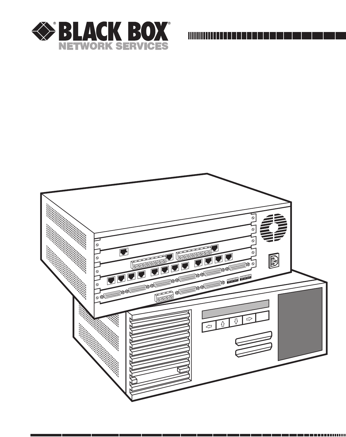
2.1 The Multiserver 5000 (Base Unit)The Multiserver 5000 is a communications-networkmultiplexor. It integrates data, voice, fax, andexternal LAN brid
Multiserver 5000208Figure B-11. RS-232/V.35 Converter to DTE with Male-to-Female Cable.(EHN071-005M).Cabling for Converters (continued)21151434171624
Appendix B: Cabling Diagrams209Figure B-12. X.21 Converter to DCE with Female-to-Male Cable(EVNX21-003M-MF, included with adapter).Cabling for Conve
Multiserver 5000210Figure B-13. Tandem Cable Diagram.Cabling for Use with Tandem12345678202225123456127820222525-PIN CONNECTOR(MALE)25-PIN CONNECTOR(
Appendix C: Defaults211System AdministrationPort ConfigurationMenu Item
Multiserver 5000212System Administration (continued)Command Facility ParametersMenu Item
Appendix C: Defaults213Asynchronous Channel ConfigurationChannel CharacteristicsMenu Item
Multiserver 5000214Synchronous Channel ConfigurationChannel CharacteristicsMenu Item
Appendix C: Defaults215Synchronous Channel Configuration (continued)RTS/CTS Menu Item
Multiserver 5000216Synchronous Channel Configuration (continued)H-P SyncMenu Item
Appendix C: Defaults217Synchronous Channel Configuration (continued)TDMMenu Item
CHAPTER 2: Introduction21three (3) high-speed interconnect links (aMultiserver-to-Multiserver connection) in ports A1to A3, five (5) mux links (a Mult
Multiserver 5000218Voice/Fax ModuleKTS InterfaceMenu Item DefaultMode
Appendix C: Defaults219Voice/Fax Module (continued)Voice/Fax Node ParametersMenu Item
Multiserver 5000220NMS ModuleCommand PortMenu Item DefaultData Rate .
Appendix D: Messages221The messages are divided into two categories, screen display messages and LCD messages. Included in theselists are messages r
Multiserver 5000222ni ADB PROCESS ABORTED Event An attempt to place a call on the dial lines hasLINK # ci failed. This message is displayed by the ca
Appendix D: Messages223CHANNEL NOT INSTALLED Info An attempt has been made to configure or test avoice/fax port and the port number selected is not a
Multiserver 5000224CONNECT FAIL MATRIX n/c Event The matrix connection request made by the localport did not complete successfully. Also, thepassword
Appendix D: Messages225ni DIALING TX SECONDARY Info The modem is dialing the secondary TX dialLINK # ci line number. This usually indicates that the
Multiserver 5000226INCOMPATIBLE Info You are trying to connect a mux link to theLINK TYPES port configured as an interconnect link or vice versa.INCOR
Appendix D: Messages227ISU LOCAL LOOPBACK Diagnostic The ISU on link ci has been placed in localACTIVE LINK # ci loopback.ISU LOCAL Diagnostic This t
Multiserver 500022PRODUCT NAME ...ORDER CODEMS1 56K CSU/DSU Module (cabling included) ...
Multiserver 5000228LOCAL DIGITAL Diagnostic The RD signal is being internally looped to theLOOP LINK # ci TD signal and transmitted onto the VF line.L
Appendix D: Messages229NO ASYNC CHANNELS Info A port or ports in the range selected is notWITHIN RANGE configured for async.NODE-CHANNEL NOT AVAILABL
Multiserver 5000230OUTPUT DATA TEST COMPLETE Diagnostic An async channel output test is complete.PRESS BREAK TO Diagnostic To terminate a channel loop
Appendix D: Messages231RESET REQ’D Info You have changed the sync protocol and did notperform a reset. It is necessary to reset the nodebefore proce
Multiserver 5000232ni TRANSMITTER RING Event A call is coming in on the transmitter side.DETECT LINK cini TX CONNECTION MADE Event A successful call w
Appendix D: Messages233VOICE CHANNEL [n/c] Event Voice/fax port c on node n has clearedTEST CLEARED (stopped) the current diagnostic test.<WAITIN
Multiserver 5000234LCD MessagesMESSAGE TYPE:Alarm Vital to the system’s operation; may cause an interruption to that operation.Event Occurs in the reg
Appendix D: Messages235ARE YOU SURE? Info A reset is requested. If the answer is yes, press theEXEcute key to proceed with the reset. If theanswer
Multiserver 5000236INTEGRAL DEVICE NOT Info You have attempted to select an Integral DeviceYET DEFINED Menu in which the device has been detected by t
Appendix D: Messages237LOCAL LINK RESET ci Event or Alarm Local link ci has been reset.NEW DATE: nn/nn Event or Alarm Appears at the beginning of eac
CHAPTER 2: Introduction232.3 The CommPakThe Multiserver 5000 Commpak plug-in softwarecartridge contains all of the Multiserver 5000’soperating softwa
Multiserver 5000238TERMINATED Info A diagnostic test has been stopped (terminated).VOICE CHANNEL n/c Event or Alarm Termination of a busyout condition
Appendix E: Indicators239Appendix E: IndicatorsA6 A5 A4 A3 A2 A1AT BOFigure E-1. CCM Indicator Positions.CCM LED IndicatorIndicator Definition Off
Multiserver 5000240Table E-2. CCM Indicator LEDsINDICATOR STATUS EQUIPMENT STATUSAT BO A6 A5 A4 A3 A2 A110 XXXX XX1Normal equipment status0 0 1 0 0 0
Appendix E: Indicators241CCM LED Indicator Indicator Definition Off Flashing Onn1 through n12 Channel number No data activity Data activity Data acti
Multiserver 5000242LED IndicatorIndicator Definition Normal Operation Input Level Display Loopback Self-TestOK OK On or flashing On Off On if success
Appendix E: Indicators243+1 dB +OK LO RO LS RS TM OK LO RO LS RS TM-4 dBm THROUGH +1 dBm-15 dBm THROUGH -5 dBm-25 dBm THRO
Multiserver 5000244LL RT SI RD TDFigure E-5. CSU/DSU Module Indicator Positions.LED IndicatorIndicator Definition Off Flashing OnLL Local Loopback No
Appendix F: Device Applications245Extended WANG Support Feature (WANGX)The extended WANG support feature (WANGX)provides special buffer control, flow
Multiserver 5000246• HP port should be enabled when Term Type 10 isconfigured by the CPU or the terminal user.• Do not define the DC2 character for ei
Appendix G: Rackmount Installation247The MS1 Rackmount Kit consists of the followingitems:• One rackmount tray• Four screws• Four washers—nylon fille
Multiserver 5000242.8 MS1 NMS Module (MX227C)The MS1 NMS Module (network managementsystem module) fits underneath the CCM on therear panel of the Mul
Multiserver 5000248Figure G-2. The Multiserver fully installed in a 19-inch rack with the Rackmount Kit.MULTISERVER 5000EXE
APPENDIX H: Additional Information249UPGRADE INFORMATIONfrom Phase 2.5 to Phase 3.0When upgrading from a Phase 2.5 to a Phase 3.0FEATUREPAK_ cartridge
Multiserver 5000250DSR ControlWhen configuring sync channels, note that theForced On option of the DSR Control Menu forcesDSR on (high) all the time r
APPENDIX H: Additional Information251Network Management System (NETMan)MICOM’s NETMan is a software package for PCsthat manages Marathon networks. Thi
Multiserver 5000252ABR, autobaud rate detection — A process by whicha receiving device determines the data rate,code level, and stop bits of incoming
Glossary253one bit, as in quadrature amplitude modulation,the baud rate is smaller than bps.BCC, block check character — A character added tothe end o
Multiserver 5000254channel — A path for electrical transmissionbetween two or more points without commoncarrier-provided terminal equipment such as al
Glossary255CPU, central processing unit — The heart (mainprocessor) of a computer system, or thecomputer system itself. <cr>, carriage return —
Multiserver 5000256DIT, direct in termination — A service offered by aPBX which allows incoming calls to the PBX tobe routed directly to a selected te
Glossary257Multiserver network. On incoming calls, the faxsignals are routed automatically from either thePSTN or the Multiserver network to the faxm
CHAPTER 2: Introduction252.12 Manual Text ConventionsThis manual uses the following standardconventions:Partial menus are shown, and theywill be in t
Multiserver 5000258KTS, key telephone system — In industry usage, atelephone system in which the telephones havemultiple pushbuttons to allow users to
Glossary259ms, millisecond — One-thousandth of a second.multiplexor — A device that divides a compositesignal among several channels. mux — Short for
Multiserver 5000260point-to-point — A communications circuit ortransmission path connecting two points. In theMultiserver unit that connection can be
Glossary261RS-422 — An EIA-recommended standard for cablelengths that extended the RS-232 50-foot limit.Although introduced as a companion standardwit
telephone interface connector — A termination onthe voice/fax module that connects the analogside of the voice/fax channel to the telephoneequipment s
Glossary263VF, voice frequency — Any frequency within thatpart of the audio-frequency range essential forthe transmission of speech of commercialquali
Banner MessageSection 13.2Review System Message LogSection 13.3Menu Functions (password)Section 13.4AdministrationSection 13.5SystemClearLatchedAlarms
Command ModeAsync Channel Loopback Local Channel Configuration Command Facility Main Menu Exit*LocalEcho*RemoteEcho*RemoteFox*LocalFox*ChannelCharac-t
1000 Park Drive • Lawrence, PA 15055-1018 • 724-746-5500 • Fax 724-746-0746© Copyright 1994. Black Box Corporation. All rights reserved.
Multiserver 500026
Multiserver 5000263.1 Initial ConsiderationsThe Multiserver 5000 offers the ability to connectone of the following units and their associated links:•
CHAPTER 3: Network Design and Topologies273.4 Syntax for Node Numbers and IDsMultiserver units and compatible multiplexorsshare the same syntax for t
Multiserver 50002FEDERAL COMMUNICATIONS COMMISSIONRADIO FREQUENCY INTERFERENCE STATEMENTThis equipment generates, uses, and can radiate radio frequenc
Multiserver 500028A3A5A4A3A5A4A1A2A1A2PORTLocal Hub Group Remote Hub GroupA1A2A1A2Figure 3-1. In this distributed star, A1 and A2 are interconnect lin
CHAPTER 3: Network Design and Topologies293.6 Examples of Network DesignsSINGLE LINK POINT-TO-POINTThe most basic of topologies is the point-to-point
Multiserver 500030DUAL LINK POINT-TO-POINTFigure 3-5 illustrates a dual-link, point-to-point application. All traffic between Multiserver nodes is loa
CHAPTER 3: Network Design and Topologies31STRINGIf several Multiserver units are strung together, a string topology is created (Figure 3-6). The limit
Multiserver 500032STARThe star topology (Figure 3-9) is a network with a single major center (hub) connected to (up to) five accesspoints. The Multise
CHAPTER 3: Network Design and Topologies33DISTRIBUTED STARIf two Multiserver star networks are connected, the topology can be described as a distribut
Multiserver 500034This chapter explains how to install the Multiserverbase unit. Once installation is completed, you willbe ready to configure. It is
CHAPTER 4: Base-Unit Installation354.2 CommPak Cartridge Installation andRemovalINSTALLING THE COMMPAK CARTRIDGEThe CommPak cartridge contains the op
Multiserver 500036On the front of the unit is a liquid-crystal display(LCD). After the unit completes its internal tests,the clock will start and the
CHAPTER 4: Base-Unit Installation374.6 Identify the Module Locations and Channel NumbersMODULE LOCATION AND NOMENCLATUREThere are five chassis positio
Table of Contents31. SpecificationsMultiserver 5000 (Base Unit) ...
Multiserver 500038the Multiserver 5000.• The CCM module has six connectors and islocated in module location A. From left to rightthese connectors are
CHAPTER 4: Base-Unit Installation39J13J11J14BATTERYJ15E1PORT 6PORT 5PORT 4PORT 3PORT 2PORT 1J17 J18J1 J2 J3 J4J16Figure 4-9. The CCM Board. The front-
Multiserver 5000405.1 Module Stacking OrderAlthough you are not actually installing themodules yet, it is important to become familiar withthe five c
CHAPTER 5: Module Installation415.2 Module-Location Switch SettingsEach expansion module has a module-locationswitch group S1 that informs the softwa
Multiserver 5000425.3 Inter-Module Stacking ConnectorsThe modules are powered via the stackingconnector located on the front right side lookingfrom t
CHAPTER 5: Module Installation435.4 Blank Back PanelThe unit is delivered with blank back panels toeliminate an open area in the rear of the unit whe
Multiserver 5000445.5.1 UNPLUG THE MULTISERVERRemove the power cord from the wall outlet.The Multiserver unit contains electrosensitivecomponents tha
CHAPTER 5: Module Installation45cover. The delicate metallic finger stocks are locatedat the front and rear of the cover. They are neededto make conta
Multiserver 5000465.5.4 REMOVE SPACERSInside the front of the Multiserver unit, there aresix spacers for positioning the modules (see Figure 5-9). To
CHAPTER 5: Module Installation475. Disconnect the fan connector from the CCM.6. Disconnect the 34-pin NMS module ribbon cable,if it is installed.7. Un
Multiserver 500043.5 Default Node Numbers and Node IDs ...273.6 Examples of
Multiserver 5000485. Connect the 26-pin LCD ribbon cable to theCCM.6. Connect the fan connector to the CCM.7. Connect the 34-pin NMS Module ribbon cab
CHAPTER 5: Module Installation495.6.4 REMAINING SPACERSWhen finished installing the modules, reinstall anyremaining spacers.5.6.5 INSTALLING BLANK B
Multiserver 5000505.6.6 PUT THE COVER BACK ON1. Be sure that all spacer positions have been filledbefore replacing the cover to ensure propermodule c
CHAPTER 5: Module Installation515.7 Converters (Optional Equipment)The converter is attached externally to theMultiserver unit. The V.35 and X.21 Con
Multiserver 5000526.1 Multiserver Base Unit LocationYour Multiserver should be installed at its location.If you have a Rackmount Kit, install it now
CHAPTER 6: Getting Started536.3 The Command FacilityThe Command Facility contains menus to configurethe ports, node, and data channels. You will need
Multiserver 500054ACCESS THE COMMAND FACILITY VIA $CMDPress <cr>. At the ENTER CLASS prompt, enter$CMD.There is no default password. Just press
CHAPTER 6: Getting Started556.4 Reset DefaultsUse one of the following methods to ensure that theMultiserver’s configurations are set to standarddefa
Multiserver 5000566.5 Name the Local NodeYou will need to assign the local node a number andname to differentiate it from remote nodes. Referto the w
CHAPTER 6: Getting Started57When you have entered a valid number and ID, thefollowing message will appear:Enter Y to store your changes and to reset t
Table of Contents (continued)Table of Contents55.5.7 Removing the CCM...
Multiserver 5000586.6 Quick SetupCAN YOU DOAQUICK SETUP?A quick installation can be done to get a point-to-point Multiserver network up and running i
CHAPTER 6: Getting Started59THE FORCE-CONNECTIONThe force-connection is accessed through theCommand Facility. Press <cr>. After all channels hav
Multiserver 5000607.1 OverviewThis chapter discusses setting up your Multiservernetwork before it is installed in remote locations.Configuring and te
CHAPTER 7: Bench Configuration and Testing6112 456ABCDE31 2 3 4 5 6 7 8 9 10 11 1212KTSOPXSB M E SG R1 T1 R TVOICE CHANNEL 1KTSOPXSB M E SG R1 T1 R TV
Multiserver 5000627.2 Using CSU/DSUs with the Interconnect LinkFigure 7-2 illustrates a Multiserver network, with aMultiserver 5000 as the central hu
CHAPTER 7: Bench Configuration and Testing637.3 Using Modems with the Interconnect LinkFigure 7-3 illustrates how modems can be used toconnect two Mu
Multiserver 5000647.4 The Sync Data ChannelBecause of the myriad of different protocol andequipment combinations available for sync datachannels, the
CHAPTER 7: Bench Configuration and Testing6512 456ABCDE312 456ABCDE3Local MultiserverAsync terminal(DTE, DB25)Async terminal(DTE, DB25)Async terminal(
Multiserver 500066The Multiserver will connect port A4 to port A5and you will get a CONNECTED message. Datacan now be exchanged between the two datach
CHAPTER 7: Bench Configuration and Testing6712 456ABCDE312 456ABCDE3MS RLB COMMPAKMS RLB COMMPAKFigure 7-6. Testing the RLB Module in a ThinNet enviro
Multiserver 50006External CSU/DSU to Internal CSU/DSU ...62External CSU/DSU
Multiserver 5000687.6 Testing the RLB ModuleDuring Bench Configuration, you can quickly testyour MS RLB Modules to verify that they areworking proper
CHAPTER 7: Bench Configuration and Testing697.7 Voice/Fax ChannelsVoice/fax channels are by default strapped forKTS—the setting for standard telephon
Multiserver 5000708.1 Types of LinksThere are three types of links in the Multiserversystem:An Interconnect Link connects two Multiservers(usually ov
CHAPTER 8: Link Configuration718.4 Port ConfigurationBefore the link is installed, the port assigned to thelink must be configured. Configure the por
Multiserver 5000728.5 The Interconnect LinkPORT CONFIGURATION FOR THE INTERCONNECT LINKThe Interconnect Link is for connection to anotherMultiserver.
CHAPTER 8: Link Configuration73When the local Multiserver 5000 connects toanother Multiserver, it scans the remote Multiserver,reads the node ID and n
Multiserver 500074Next, select option 3 from the remote CommandFacility menu.It may seem to be a paradox to use the term “localnode” when configuring
CHAPTER 8: Link Configuration758.6 The Mux LinkPORT CONFIGURATION FOR THE MUX LINKThe mux link is for connecting the Multiserver to afeeder mux. The
Multiserver 500076FEEDER MUX NODE IDSYou should renumber and rename a feeder muxafter configuring its link. Mux and X.21 links havedefault numbers and
CHAPTER 8: Link Configuration778.7 The X.21 LinkINTRODUCTION TO X.21 Unlike the mux links (leased-line links), which arepermanently connected, X.21 i
Table of Contents (continued)Table of Contents7Introduction to X.21 ...
Multiserver 500078X.21 LINK PARAMETERS1. LOCAL X.21 CONNECT MODE [DATA ACTIVITY CONNECT]2. LOCAL X.21 NUMBER OF RETRIES [20]3. MB2 X.21 CONNECT MODE [
CHAPTER 8: Link Configuration79Table 8-2. X.21 Link Parameters (continued)Option Default Description2. Local X.21 Number 20 This option selects the nu
Multiserver 500080INSTALL THE X.21 LINKAssuming that you have installed and configuredthe modem for the X.21 link, connect the cable.In X.21 link oper
CHAPTER 8: Link Configuration818.8 Review Link ConfigurationTo review node configuration, select option 2,Status/Statistics, from the Command Facilit
Multiserver 500082To configure data channels, the local node must benamed. If you have not already named the localnode, refer to Section 6.6, Naming t
CHAPTER 9: Data-Channel Configuration839.2 Synchronous ChannelsSync is supported only when directly attached to aMultiserver. Feeder muxes can only s
Multiserver 500084Table 9-1. Sync Protocol OptionsOption Description1. DLC Typical DLC protocols are SDLC and HDLC. The DLC protocol options are stand
CHAPTER 9: Data-Channel Configuration85performed after changing the port configuration tosync. Leave the menu and perform the reset, and trythis proce
Multiserver 500086Table 9-3. Sync Channel CharacteristicsOption Protocol Default DescriptionData Rate DLC 2400 Sets data rate (in bps) for the port. N
CHAPTER 9: Data-Channel Configuration87Table 9-3. Sync Channel Characteristics (continued)Option Protocol Default DescriptionInterface DLC TO DTE Set
Multiserver 50008Fixed Destination Connection ...112Class
Multiserver 500088Table 9-3. Sync Channel Characteristics (continued)Option Protocol Default DescriptionNumber of ASCII Bisync 1 Sets the number of le
CHAPTER 9: Data-Channel Configuration89MICOM Voice ENABLETable 9-3. Sync Channel Characteristics (continued)Option Protocol Default DescriptionDSR Con
Multiserver 500090Table 9-5. Synchronous ClockingCable PartConfiguration Description of Use Cable Diagrams for Clocks (1) NumberNormal Synchronous Use
CHAPTER 9: Data-Channel Configuration91Table 9-6. CCM and 6-Channel CEM (MX215C only)Local Sync Channel Interface Configured to DTEMultiserver DTECons
Multiserver 500092Table 9-7. CCM and 6-Channel CEM (MX215C only)Local Sync Channel Interface Configured to DCEMultiserver DCEConstant ControlledPin I/
CHAPTER 9: Data-Channel Configuration939.3 Asynchronous ChannelsBefore configuring an async channel, be sure thatthe port is configured for async (fr
Multiserver 500094ASYNC CHANNEL CHARACTERISTICSThe Channel Characteristics Menu is accessed fromthe Async Channels Menu as option 1. The operating par
CHAPTER 9: Data-Channel Configuration95Table 9-8. Asynchronous Channel CharacteristicsOption Default Description1. Data Rate 9600 Sets the data rate
Multiserver 500096Table 9-8. Asynchronous Channel Characteristics (continued)Option Default Description7. XON Character DC1 Selects the character for
CHAPTER 9: Data-Channel Configuration97Autobaud Rate Detection (ABR). The Multiserver5000 has the capability of automaticallydetermining the data rate
© 2020, manymanuals.com. All rights reserved. | 0.917 s |
 Manymanuals.com
 Manymanuals.de
 Manymanuals.fr
 Manymanuals.it
 Manymanuals.pl
 Manymanuals.cz
 Manymanuals.es
 Manymanuals-pt.com
Comments to this Manuals